The left pair of gears makes external contact, and the right pair of gears makes internal contact

Gears are machine elements that transmit motion by means of successively engaging teeth. The gear teeth act like small levers.
Gears may be classified according to the relative position of the axes of revolution. The axes may be
Gears for connecting parallel shafts
The left pair of gears makes external contact, and the right pair of gears makes internal contact
Gears for connecting intersecting shafts

Neither parallel nor intersecting shafts

Figure 1 shows two mating gear teeth,
Although the two profiles have different velocities V1 and V2 at point K, their velocities along N1N2 are equal in both magnitude and direction. Otherwise the two tooth profiles would separate from each other.
Point P is very important to the velocity ratio, and it is called the pitch point. Pitch point divides the line between the line of centers and its position decides the velocity ratio of the two teeth. The above expression is the fundamental law of gear-tooth action.
For a constant velocity ratio, the position of P should remain unchanged. In this case, the motion transmission between two gears is equivalent to the motion transmission between two imagined slipless cylinders with radius R1 and R2 or diameter D1 and D2. We can get two circles whose centers are at O1 and O2, and through pitch point P. These two circle are termed pitch circles. The velocity ratio is equal to the inverse ratio of the diameters of pitch circles. This is the fundamental law of gear-tooth action.
The fundamental law of gear-tooth action may now also be stated as follow (for gears with fixed center distance):
The common normal to the tooth profiles at the point of contact must always pass through a fixed point (the pitch point) on the line of centers (to get a constant velocity ration).
To obtain the expected velocity ratio of two tooth profiles, the normal line of their profiles must pass through the corresponding pitch point, which is decided by the velocity ratio. The two profiles which satisfy this requirement are called conjugate profiles. Sometimes, we simply termed the tooth profiles which satisfy the fundamental law of gear-tooth action the conjugate profiles.
Although many tooth shapes are possible for which a mating tooth could be designed to satisfy the fundamental law, only two are in general use: the cycloidal and involute profiles. The involute has important advantages -- it is easy to manufacture and the center distance between a pair of involute gears can be varied without changing the velocity ratio. Thus close tolerances between shaft locations are not required when using the involute profile. The most commonly used conjugate tooth curve is the involute curve
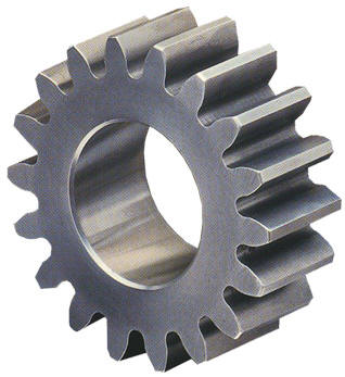
The following examples are involute spur gears. We use the word involute because the contour of gear teeth curves inward. Gears have many terminologies, parameters and principles. One of the important concepts is the velocity ratio, which is the ratio of the rotary velocity of the driver gear to that of the driven gears.
The curve most commonly used for gear-tooth profiles is the involute of a circle. This involute curve is the path traced by a point on a line as the line rolls without slipping on the circumference of a circle. It may also be defined as a path traced by the end of a string which is originally wrapped on a circle when the string is unwrapped from the circle. The circle from which the involute is derived is called the base circle.
Figure 3 shows some of the terms for gears.
In the following section, we define many of the terms used in the analysis of spur gears. Some of the terminology has been defined previously but we include them here for completeness.

and

Hence

where
That is, the product of the diametral pitch and the
circular pitch equals
 .
.
 :
The angle between the common normal at the point of tooth contact and the
common tangent to the pitch circles. It is also the angle between the line
of action and the common tangent.
:
The angle between the common normal at the point of tooth contact and the
common tangent to the pitch circles. It is also the angle between the line
of action and the common tangent. Table lists the commonly used diametral pitches.
| Coarse pitch | 2 | 2.25 | 2.5 | 3 | 4 | 6 | 8 | 10 | 12 | 16 |
| Fine pitch | 20 | 24 | 32 | 40 | 48 | 64 | 96 | 120 | 150 | 200 |
Figure 4 shows two meshing gears contacting at point K1 and K2.
To get a correct meshing, the distance of K1K2 on gear 1 should be the same as the distance of K1K2 on gear 2. As K1K2 on both gears are equal to the base pitch of their gears, respectively.